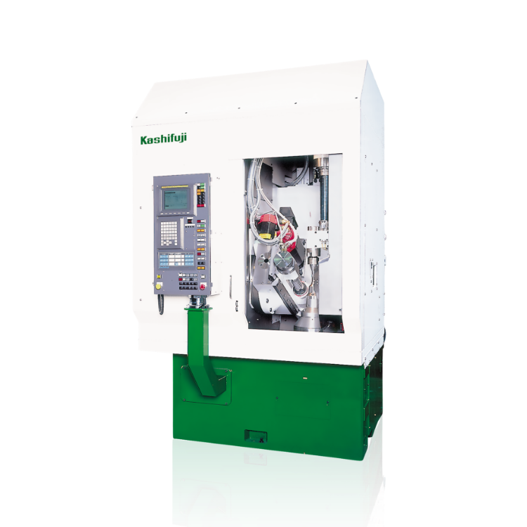
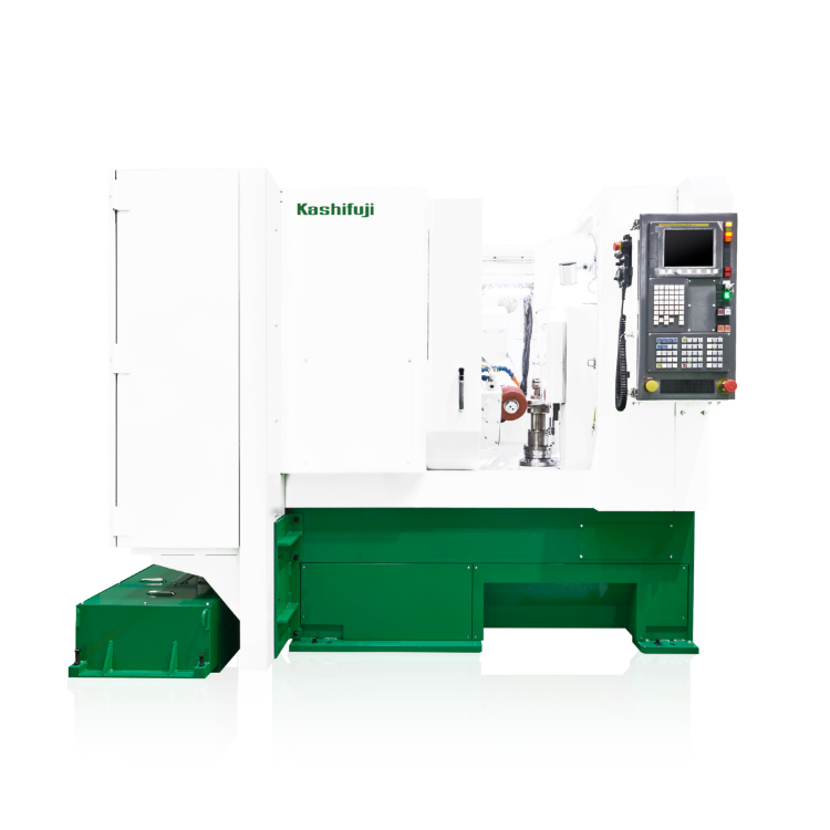
6 Axis-CNC Hobbing Machine
KN81 / 121
High-Speed and High-Precision Hobbing – Pushing the Limits
- Max. Workpiece Diameter
- 80 / 120mm
- Max. Workpiece Module
- 4
Feature
For details, click on the Icon.
-

Vertical
Hob Machine -

Hand
Scraped
Guideways -

Zero
Backlash
Table -

Auto-mation
-

In Machine Chamfering Unit
-

Hard Hobbing
-

Program
Typical Parts Hobbed
Typical Parts Hobbed
EV Gear
Compact Reduction Gear
Steering Pinion
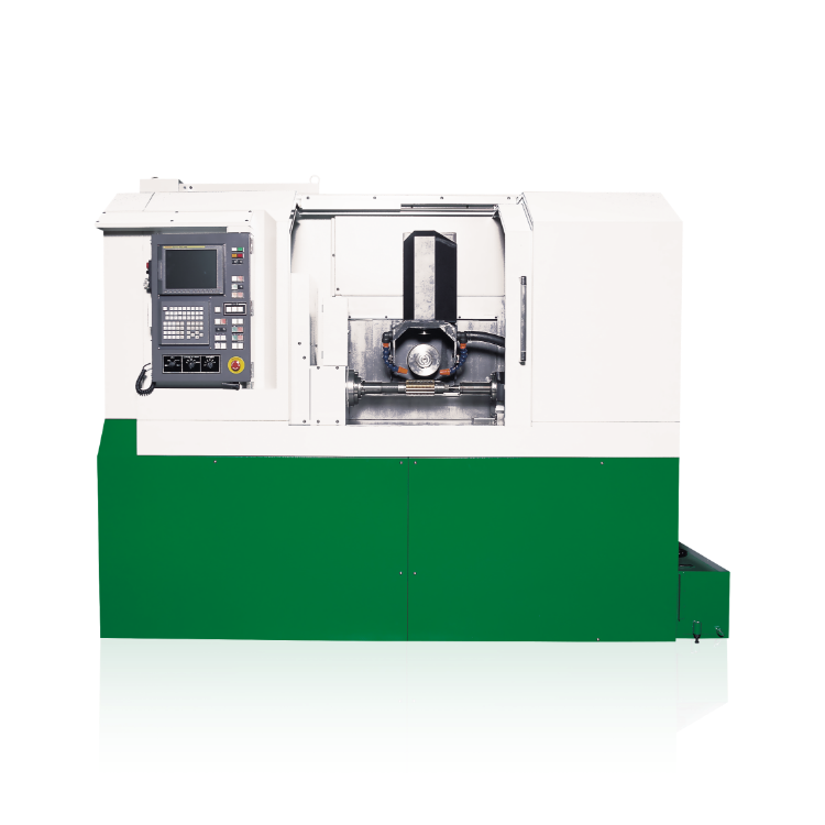
Improved Machining Accuracy
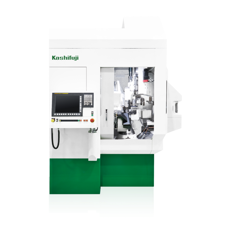
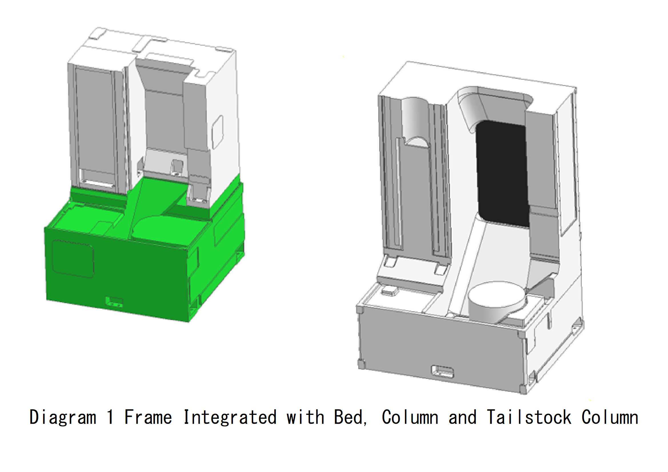
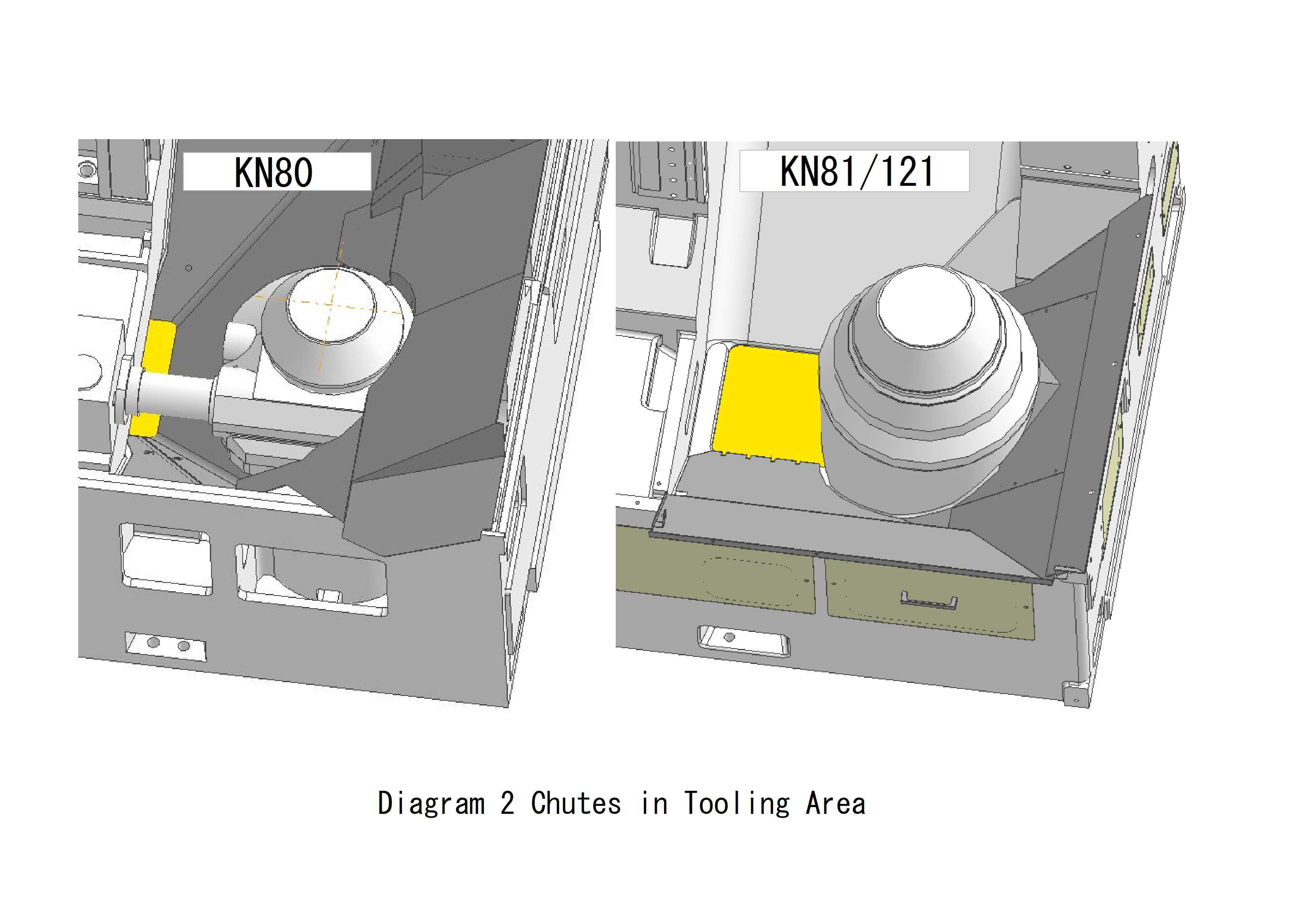
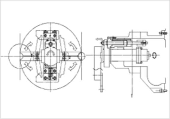
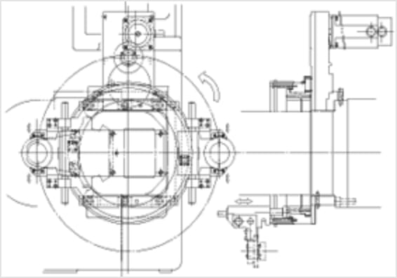
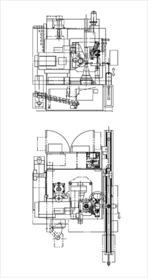
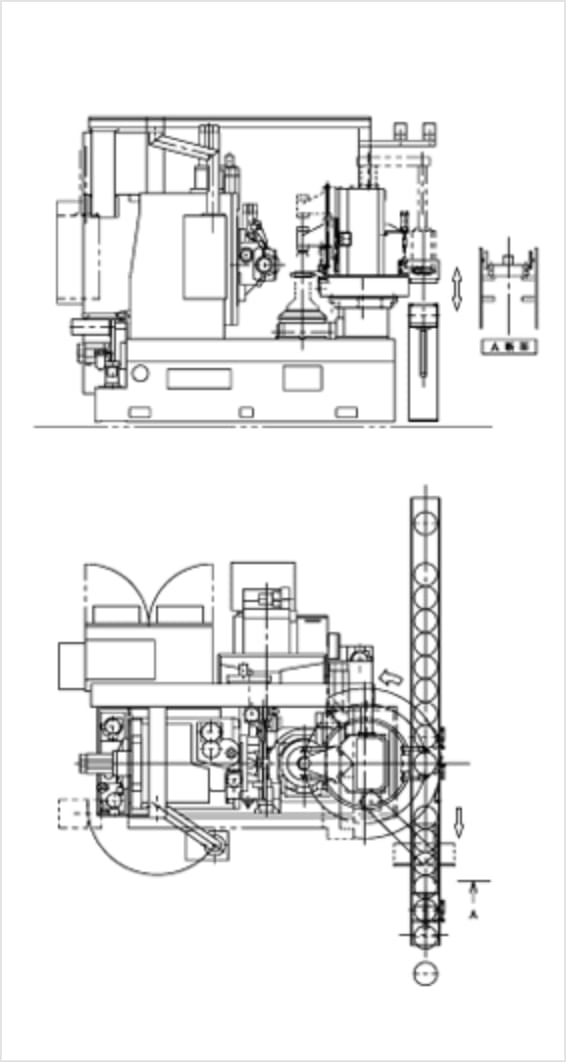
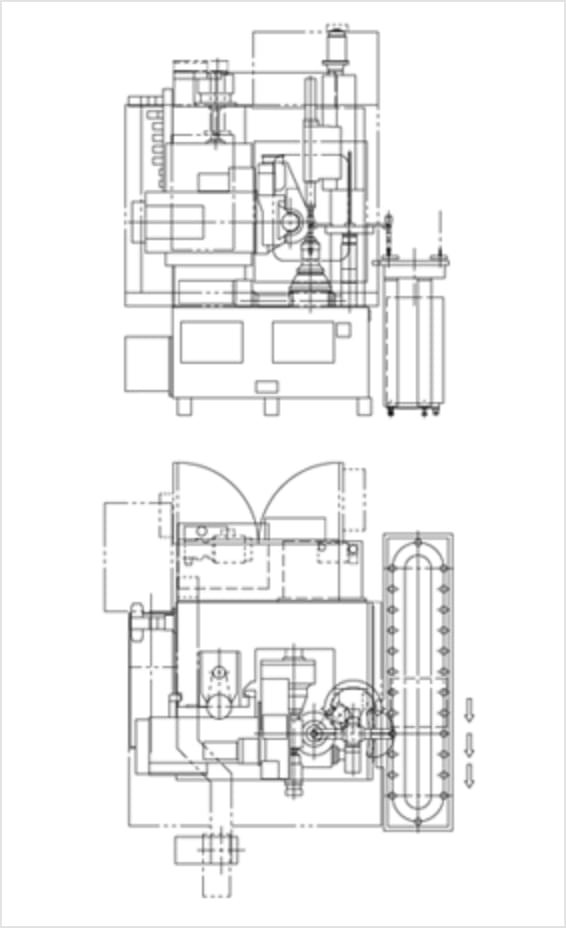
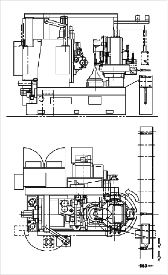
A New Frame (Diagram 1) is integrated with bed, column and tailstock column creating excellent accessibility/workability. This allows for a high degree of thermal stability. Structural analysis optimizes the rib arrangement in the castings which allows high rigidity. Also, by adopting “in-machine” inclined chutes with fewer steps/seams with a large chip exhaust opening, chips are smoothly discharged during dry cutting. (Diagram 2). Thermal deformation caused by hot cutting chip accumulation is suppressed, and stable machining accuracy can be achieved.
The work table axis is a direct drive mechanism utilizing a built-in servo motor, enabling high-speed and high-precision hobbing. The radial rigidity of the hob spindle axis has been improved by 1.8 times compared with the conventional machine by increasing the spindle and its bearing diameters. Even in Hard Hobbing of heat-treated gears, it is possible to deliver machining accuracy higher than that of conventional machines.
Improved Standard specifications
To reduce machining and idle times, standard specifications have been improved, such as increasing the maximum rpm of the hob and work table axes and increasing the feed rate of each axis, which contributes to improved productivity. The hob shift travel is now 150mm, a 20mm increase over to the conventional machine, which allows for longer hob tools, reducing frequency of hob re-sharpening. The hob cutter head now has a vertical stroke of 250mm, an increased by 50mm over the standard. The hob head stroke can be extended to a max. of 400mm as an optional feature. This allows for long shaft components such as motor shafts for electrical vehicles. In addition, by minimizing the hob head interference area between the hob and work table, a small-diameter part can be machined.
Compatible with High-Speed and High-Precision (Optional Specifications)
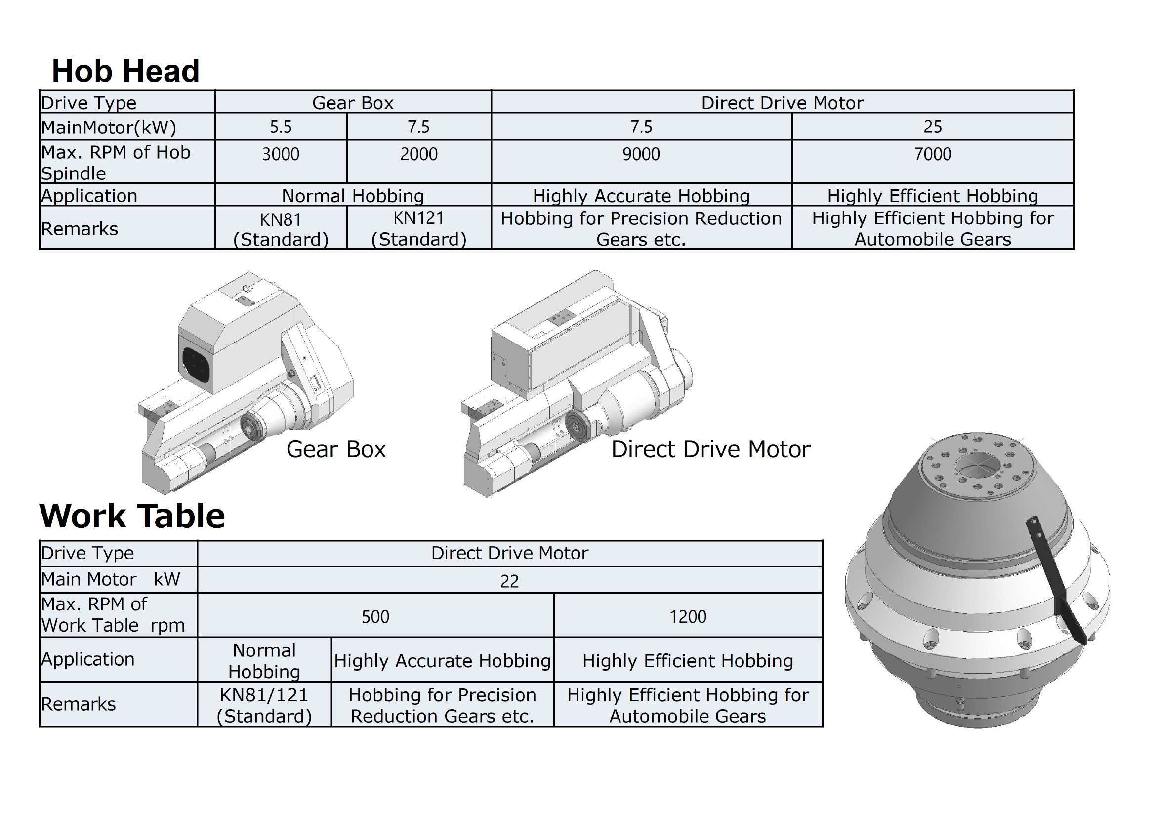
A 9,000 rpm hob head with a 7.5kW built-in motor for high-speed and high-precision machining or the 7,000 rpm hob head with a 25kW built-in motor specialized for high-efficiency machining can be selected. Hard hobbing (heat-treated gears) or shaving-less machining before heat treatment is available. The 1,200rpm high-speed work table with high-efficiency machining can also be selected. Additionally, linear scales can be installed on the hob vertical movement axis, hob radial movement axis, and hob shift axis for the full-closed loop control, allowing for increased high precision machining. We are continually developing and expanding optional specifications with the goal of further increasing high-speed and high-precision machining.
In-Machine Chamfering Device (Optional Specifications)
It is possible to mount a round chamfer unit that performs chamfering on the same work table as the hobbing process, and it is also possible to remove secondary burrs generated after chamfering and finish hobbing (see the video below). In addition, the lineup includes a round chamfer device mounted on a separate work table (increasing productivity), and also a tracing milling unit using a carbide end mill and a deburring unit using a rotating brush can be prepared, which can accommodate various part shapes.
Specifications
-
- Machine Type
KN81
KN121
Specs
- Max. Workpiece Diameter
-
80mm
120mm
- Max. Workpiece Module
-
4
4
- Max. axial feed travel
-
250mm
250mm
- Max. hob head swivel
-
±45°
±45°
- Max. hob size, diameter × length
-
110×180mm
110×180mm
- Max. hob shift travel
-
150mm
150mm
- Max. revolution of hob, infinitely variable
-
200~3,000rpm
200~2,000rpm
- Max. revolution of work table
-
500rpm
500rpm
- Weight
-
6,000kg
6,000kg
- Floor Space: Length x Width x Height
-
2795×1850×2600mm
2795×1850×2600mm
Product Catalog
You can download the PDF data of product catalogs by adding the desired catalog to the list and filling out the form at each download link.
-
KN81 / 121
downloadIf you want to view other catalogs or download multiple catalogs, visit the
catalog download page.
Inquiries about This Product
We are dedicated to a fast response to your request, and will make every attempt to respond in a timely manner. Requests received on Holidays or Weekends will be handled on the next business day in most cases.
-

Contact by E-mail
You can e-mail us through the forms below.
Contact FormSSL-EnabledAll your personal information entered into the forms is safely protected using a secure VeriSign SSL encryption session.
-

Contact by Phone
Head Quarters Overseas Sales Dept.+81-75-661-5271
Hours : Monday ~ Friday, 8:00 a.m. ~ 16:30 p.m. (Japan)
(Except for New Year’s, National, Summer and other Company Holidays) -

Contact by FAX
Head Quarters Overseas Sales Dept.+81-75-661-5270
Please use the FAX sheet below.
Product and Other Inquiries Request for Quotation for Spare Parts or an Order for Spare Parts
Related Products
-
KN80
6 Axis-CNC Hobbing Machine
Max. Workpiece Diameter:80mm
Max. Module:4
Products
Features:
Ideal for Hobbing Small Gears
An Energy-Saving and Complete Dry Cut Hobbing Machine
(Wet Cut Hobbing Machine or Wet/Dry Cut Hobbing Machine is optionally available.)Typical Parts Hobbed:
Steering Pinion
Geared Motor
Compact Reduction Gear
Motorcycle Gear -
KGH250
Gear Flank Finisher
Max. Workpiece Diameter:250mm
Max. Workpiece Module:4
Products
Features:
Simple & Easy Finishing of Gear Flanks
Typical Parts Hobbed:
・ Spur Gear
・ Helical Gear
・ Shaft Gear etc. -
KG253S / L
4 or 6-Axis CNC Hob Sharpening Machine
Max. Workpiece Diameter:250mm
Max. Grinding Wheel Speed:6,000rpm
Products
Features:
A Precision Hob Sharpener
Typical Parts Hobbed:
・ HSS Hobs
・ Carbide Hobs
・ Cermet Hobs
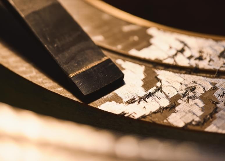
Vertical Hob Machine
Changing Fixtures, Hob Cutters or Workpieces (manual loading) is far simpler and faster than in a horizontal hobber as compared to a vertical hobber. As the workpiece /fixture are positioned vertically, they are very easy to exchange and accurately mount. The Hob Head of a vertical hobber allows great accessibility to the work table/tooling area and peripheral equipment (auto loader, transfer unit etc.) can be added without reducing operability!
Hand Scraped Guideways
Kashifuji hand scrapes the guideways on all its hobbing machines to create a platform that dampens and absorbs the intermittent cutting forces that are inherent to hobbing process. This feature allows many years of use while still maintaining superb hobbing accuracies.
Generally, machining has limited achievable accuracies due to friction created distortions and/or internal stress relief produced during the machining process. Variations of temperature and humidity during the machine process can also reduce accuracy. Kashifuji utilizes a hand scraped surface finish to assure highly accurate guideways that are not possible by any machining/grinding process.
Hand Scraping is a finish processing method that makes the guideways extremely accurate with an ideal flatness and straightness by manually removing metal in extremely small amount (1~3 micro meters) by the use of a hand tool called a "Scraper". This hand tool has a carbide tipped single edge blade with a blunt angle. This tool is used to relieve the surface tension (create numerous, evenly distributed small, shallow dips or reliefs) in the guideway surfaces. Scraping produces a very flat surface, and the "shallow divots" retain oil which creates smooth sliding surfaces while reducing wear.
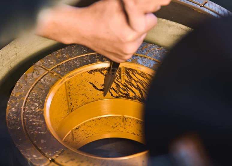
Hand scraping is a labor intensive process. The guideway surfaces are painted with a “dye” then rubbed with a reference straight edge, the dye collects on the highspots. The highspots are then removed by “hand scrapping”. This process (applying dye, rubbing & scrapping) is continually repeated until approximately 30% of the guideway surface is “relieved” producing ~70% bearing surface. This process produces an extreme flatness.
Hand scraping is referred to as a "Master's Skill". Kashifuji's skilled craftsmen are able to make accurate micro-meter scraping marks compensating for variations caused by material or temperatures changes. The "scraping pattern" produced, is often referred to as an "art form", and is unique to each craftsman. It takes many years of tedious, difficult work to acquire the experience & skill to become an accomplished Kashifuji "Scraper".
Zero Backlash Table(Work Table Backlash Eliminator)
Kashiufji designed and developed a hydraulically controlled split worm Work Table Backlash Eliminator.
This device creates a Zero Backlash condition for the work table under all cutting conditions.
The backlash eliminator suppresses work table vibrations assuring smooth and highly accurate work table rotation. The rotational accuracy of the work table will not degrade with use, as the device is self-adjusting (maintenance-free).
The backlash eliminator allows consistency in hobbing accuracies especially when hobbing large pitch gears, hobbing with a carbide skiving hob cutter and opposite hand hobbing (lead angle of a hob cutter is opposite of the helix angle of the part).
Automation
Numerous styles and types of auto loaders, conveyors or part stockers are available for automatic part transfer. All loader design are labor saving and increase efficiency.
Basic 2-Arm Auto Loader(KN80, KN152)
Basic Ring Loader
(KE201/251、KA220/400)
Transfer Example for Flat Gears
Transfer Example for Flat Gears
Transfer Example for Shaft Gears
Transfer Example for Shaft Gears
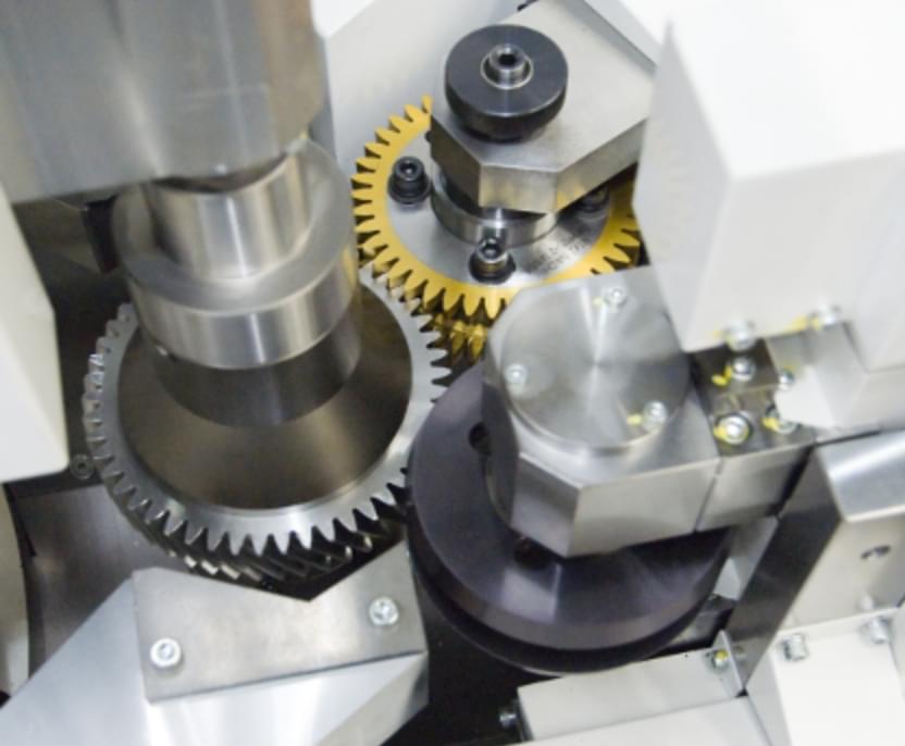
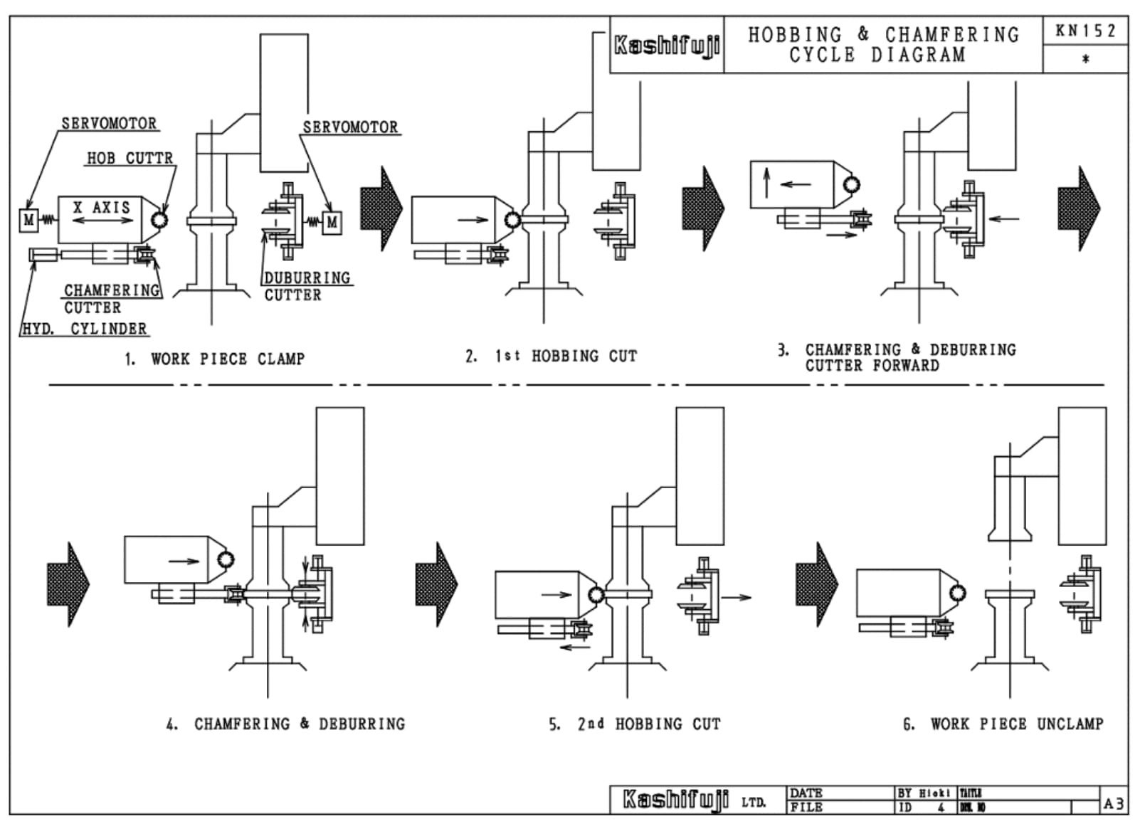
In-machine chamfering unit (optional specifications)
<Stock removal process using a chamfering cutter>
The use of an auto part loader device enables chamfering and deburring during the hobbing process. By effectively using the open space of the machine and by making the chamfering tool axis and the deburring tool axis independent, it is easy to change / adjust the tooling from the machine front operation side. In addition, the combination of hobbing, chamfering and deburring reduces the line length and cycle time.
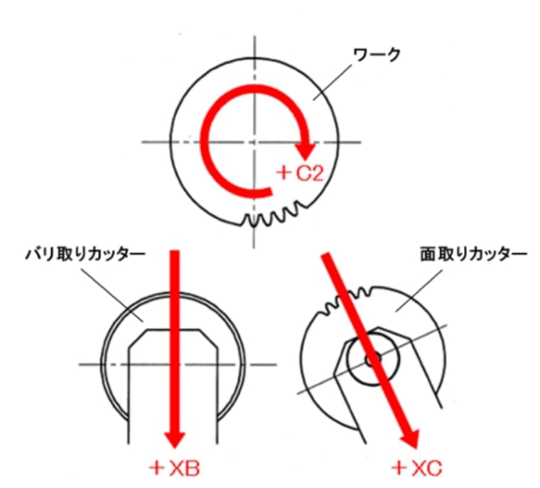
By installing a chamfering device underneath the hob head, it is possible to chamfer the part in the tooling area after hobbing and deburr the part in the open space. Additionally, the secondary burrs caused by deburring can be removed by re-hobbing. The removal of secondary burrs prevents the tooth flanks from getting damaged due to the hardened secondary burrs in the finishing processes such as gear grinding or honing, contributing to improved tool life. The combination of hobbing, chamfering and deburring reduces the line length. Also, it is possible to process a shaft gear.
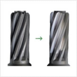
<Milling Method by tracing using a carbide rotarty end mill>
The use of an auto part loader device enables chamfering during the hobbing process. Using the machine open space effectively, the rotating carbide end mills lightly touch the rotating part allowing chamfering for both top and bottom ends of the part. Chamfering is possible using the same rotarty end mill even if the part type is chgangred.
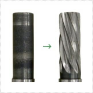
Hard Hobbing
Hard Hobbing is a finish hobbing process for hardened gears.
There are two kinds of Hard Hobbing processes that use carbide hobs. One is "Finish Hobbing" in which hardened gears are "finished" after the initial tooth cutting. The other is "Hardened Solid Gear Hobbing" where hardened solid gear blanks are finished hobbed.
Kashifuji has developed an Auto Part Orientation Device utilizing a special non-contact sensor that quickly and accurately orientates gear teeth to the hob tool.
Finish Hobbing
Hardened Solid Gear Hobbing
Auto Part Orientation Device
Programming
Programs are created by only inputting part gear data, hob data and cutting conditions. After the completion of the programs, hobbing will be automatically performed by selecting the part number.
Optional crowning, relieving and/or taper hobbing cycles are easily performed. Simple and easy-to-operate hobbing programs are available for a wide variety of production situations, from mass production to special prototype hobbing.